欢迎来到Shenzhen Riqiya Electromechanical Co., Ltd.官网!


|
|
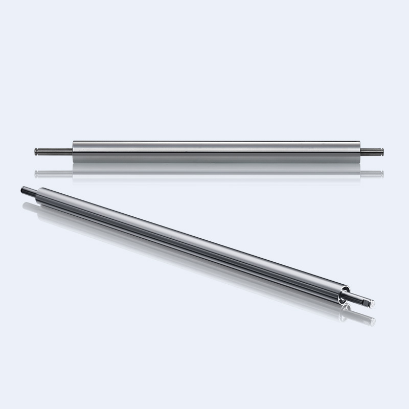
Transcribing unit (one of the core components) for copiers and laser printers. Transfer the "toner image" on the surface of the photosensitive drum to plain paper with high-voltage static electricity. This process is called "transfer". When the positively charged toner moves to the vicinity of the printing paper along with the photosensitive drum, the electrode placed behind the paper is positively charged. Because the voltage is as high as 500~1000V, the electrostatic attraction causes the paper to stick to the light guide plate. The negatively charged toner is adsorbed on the surface of the paper. Because this transfer method is related to the insulation of the paper, when the paper is damp due to the weather, the toner will not be completely and tightly adsorbed on the paper due to the leakage of the paper surface, resulting in poor print quality. There are two transfer methods, one is "corona discharge transfer" (electrode wire), and the other is "discharge rubber roller" transfer. The working principle of the two is the same. Different models have different transfer methods. The early production of laser printers mostly used the corona discharge transfer method. When the photosensitive drum carrying the toner image rotates to a position that is tangential to the transfer electrode or transfer rubber roller, a piece of printing paper is also fed between the two. At this time, the high voltage applied to the transfer electrode starts Discharge, while pushing the printing paper to the photosensitive drum, the toner image on the photosensitive drum will be attracted to the printing paper due to the transfer of the high-voltage electric field on the bottom of the printing paper to complete the secondary transfer of the toner image. The discharge polarity of the transfer electrode wire or transfer rubber roller is the same and negative, but this negative voltage is higher than the negative voltage in the exposure area of the photosensitive drum, so that while pushing the printing paper to the photosensitive drum, it also reduces The toner is attracted to the printing paper as much as possible.
is provided with a vertical drive shaft accommodating hole and a gear cavity, the gear cavity is connected to the lower end of the drive shaft accommodating hole and is equipped with a bevel gear mechanism, the bevel gear mechanism For transmitting the power of the drive shaft to the propeller shaft, the drive shaft is supported in a bearing for rotation in the drive shaft accommodating hole, and the bearing is fixed and held in the drive shaft accommodating hole. It is characterized in that: a bearing fixing element is used to hold the bearing in the drive shaft accommodating hole so that the bearing cannot move longitudinally in the drive shaft accommodating hole; and a cover element, the drive The shaft passes through the cover element, and the cover element is arranged above the bearing fixing element and closes the upper end of the opening of the drive shaft containing hole in a liquid-tight manner.
Optimization of drive shaft structure
The drive shaft relies on splines and taper shafts to cooperate with the planet carrier to transmit torque, and the taper fits often Since the eccentric bolts are loose and worn, they cannot transmit torque. Therefore, it is necessary to improve the structure of the drive shaft. The automatic selection of drive shaft is included. The taper part of the drive shaft is removed, and the drive adapter plate and the spline shaft are designed as two separate parts. The adapter plate is designed as an internal spline groove that matches the drive shaft spline, and the drive shaft spline is designed as a full-body spline to transmit torque. , The torque is completely transmitted by the cooperation of the spline shaft and the planet carrier, and the spline shaft will no longer cause stress concentration due to the variable cross-section and uneven strength of the tapered shaft, thereby improving the strength of the drive shaft.
Car drive shaft
The transmission device designed to drive the wheels is located at the end of the car’s drive train, and its function is to reduce the torque It is transmitted from the differential axle gear to the driving wheels. In the split drive axle and the steering drive axle, the transmission device for driving the wheels includes a half shaft and a universal joint transmission device, and a constant velocity universal joint is often used. The automatic selection of drive shaft is included. In general non-disconnected drive axles, the transmission device that drives the wheels is the half shaft. At this time, the half shaft connects the differential half shaft gear with the hub. On a drive axle equipped with a wheel reducer, a half shaft connects the side gear with the driving gear of the wheel reducer.
The semi-axes of ordinary non-disconnected drive axles are divided into semi-floating, 3/4-floating and Three types of full floating. The semi-floating semi-axle is directly supported on the bearing placed in the inner hole of the outer end of the axle housing with a journal close to the outer end, and the end is fixed with the wheel hub by a journal with a tapered surface and a key, or with a flange It is directly connected to the wheel disc and brake drum). Therefore, in addition to transmitting torque, the semi-floating axle shaft must also bear the bending moment transmitted from the wheels. It can be seen that the load on the semi-floating semi-bearing is complex, but it has the advantages of simple structure, small mass, compact size, and low cost. It is used for cars and light trucks with smaller mass, better service conditions, and low load-bearing capacity.
下一篇:没有了!